The New Binocular Chair
In the late 1980's, Pierre Schwaar was a local legend around the Phoenix telescope maker's community. His optics were exemplary and his stream of new, innovative ideas could make NASA take notice. He was a force of nature among telescope makers, coming up with a 16" F/5 "Telescope-Go-Round", the "Big Foot" mount and his 8" F/4.2 Binocular Chair. He tinkered constantly, ever refining and tweaking his inventions to work better and better.
While there was never a doubt of his mirror making abilities, there was some about his mechanical skills. Some of his tinkering was due to necessity-fatally flawed details in engineering on the path from his inventive mind and his limited materials. While his workmanship was high in quality, the design phases were somewhat limited. Plans went from his head to the cutting table or lathe, without much consideration given to fine details.
This is so much the tragedy, since many parts from one project went to build the next. Sometimes it worked, sometimes not.
I found this out in the first restoration of the BinoChair. I spent 5 years, off and on, working on it, only to see the design flaws take their toll upon completion. It was my intent then and there to do a complete structural analysis of the system as a whole, and rebuild the chair to make it more user friendly.
The results of this redesign will be presented here. Click on images to enlarge.
|
|
Pierre's chair in ~1990. |
 |
 |
|
| First Draft | Basic Redesign | |
 |
 |
|
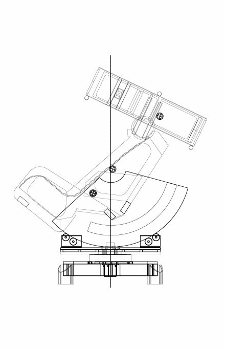
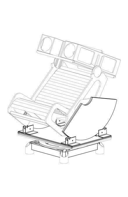
| Current Configuration | 8/12/12 |
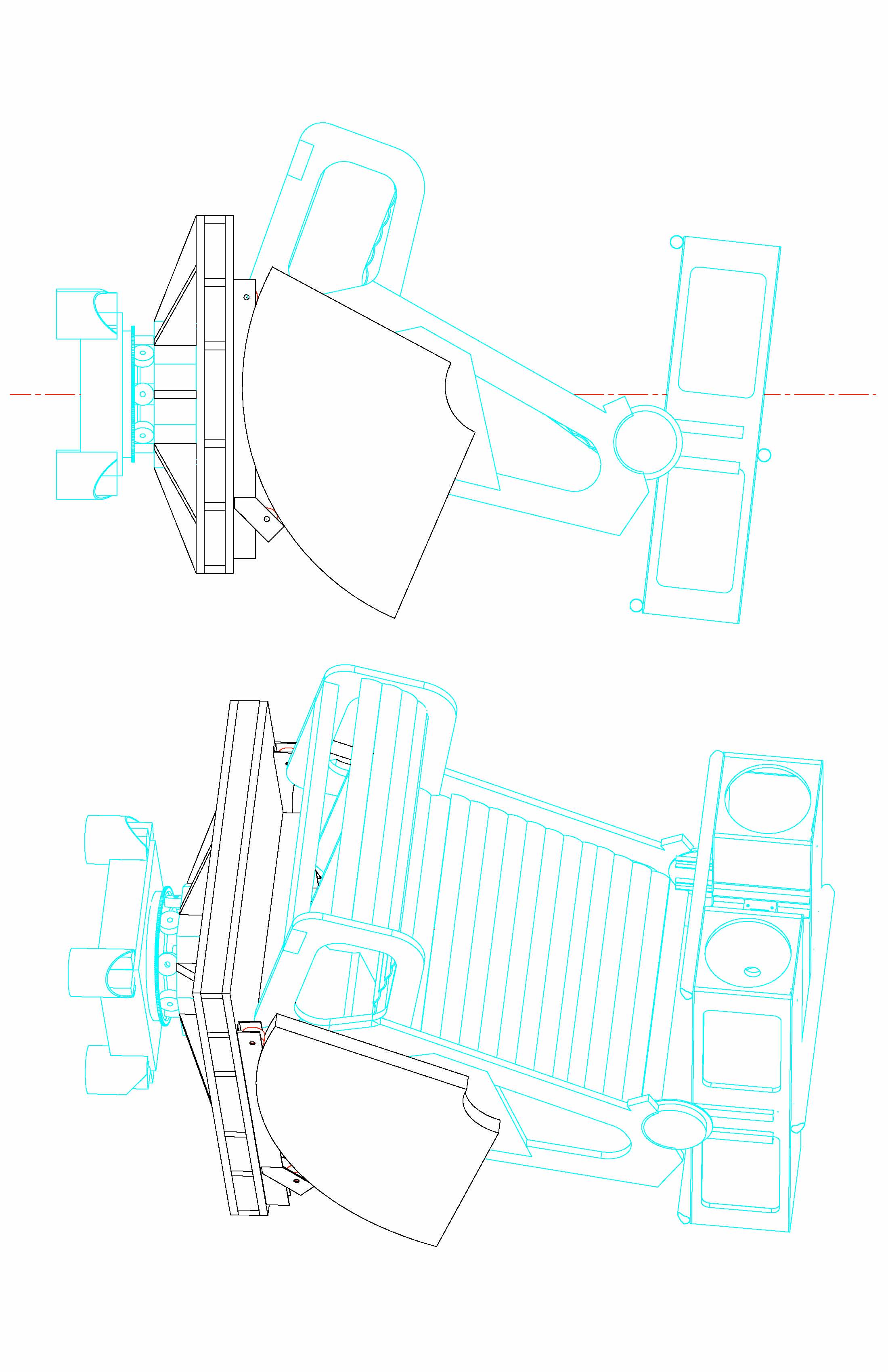
The above images show something of the progression of ideas that ran through my head in redesigning the chair. Several options were explored initially, but this one made it to the drawing board. The first draft used the existing chair, base and drive system, while replacing the azimuth box with a torsion box for stiffness and a larger altitude bearing for stability. The blue lines indicate what stays the same and the black indicate the changes.
The second draft show the entire base being replaced after studying the balance characteristics of the first draft. Making the base wider and changing the drive system made it a LOT more stable, lower to the ground and smoother in azimuth. The base design was built over the thanksgiving weekend in 2007.
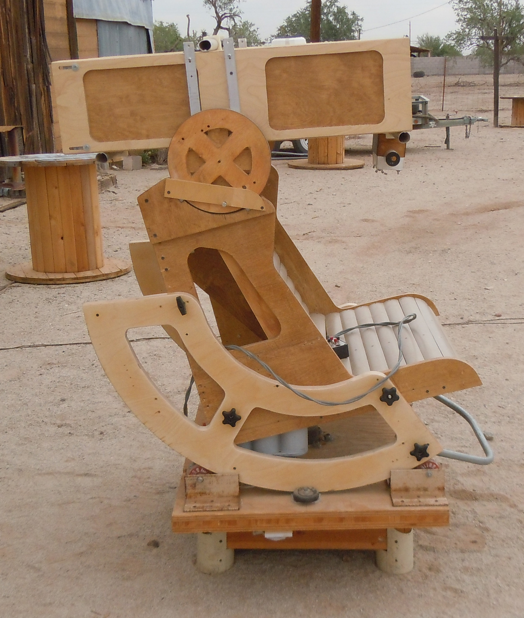
The current configuration is shown in a CAD drawing. lick for a PDF. A picture taken 8/12/12 is also shown.
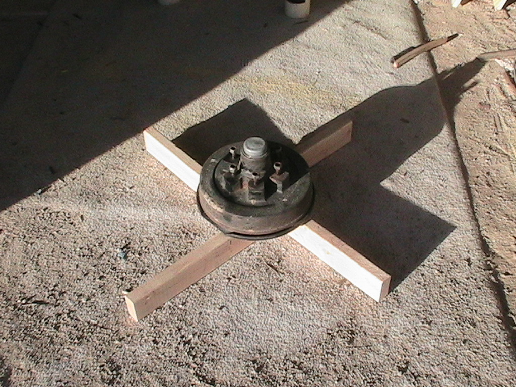
The Base
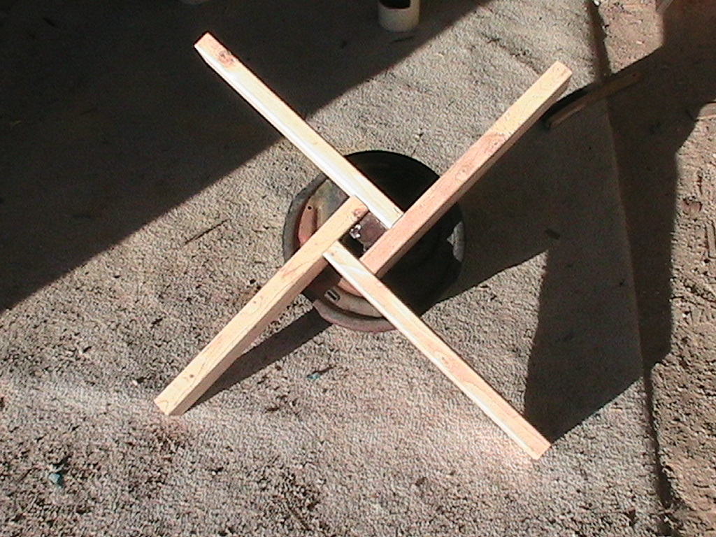 |
The basic base, showing the wheel mounted on 2x4's. |
 |
From the underside. |
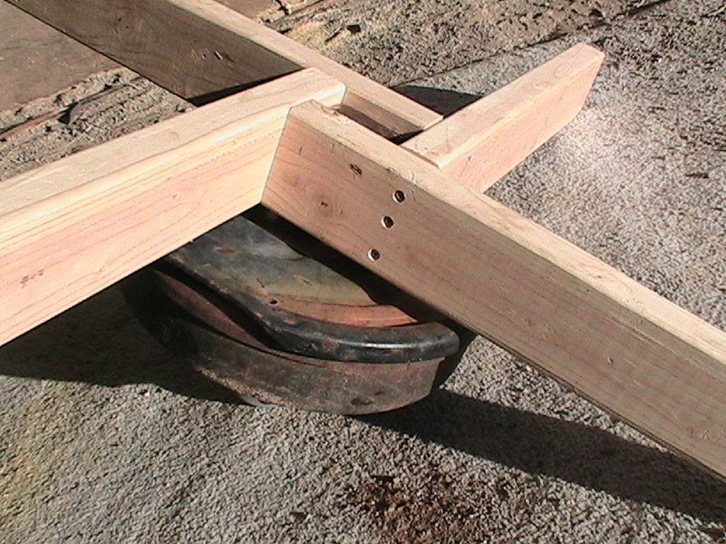 |
Detail shows screws, but glue was added later. |
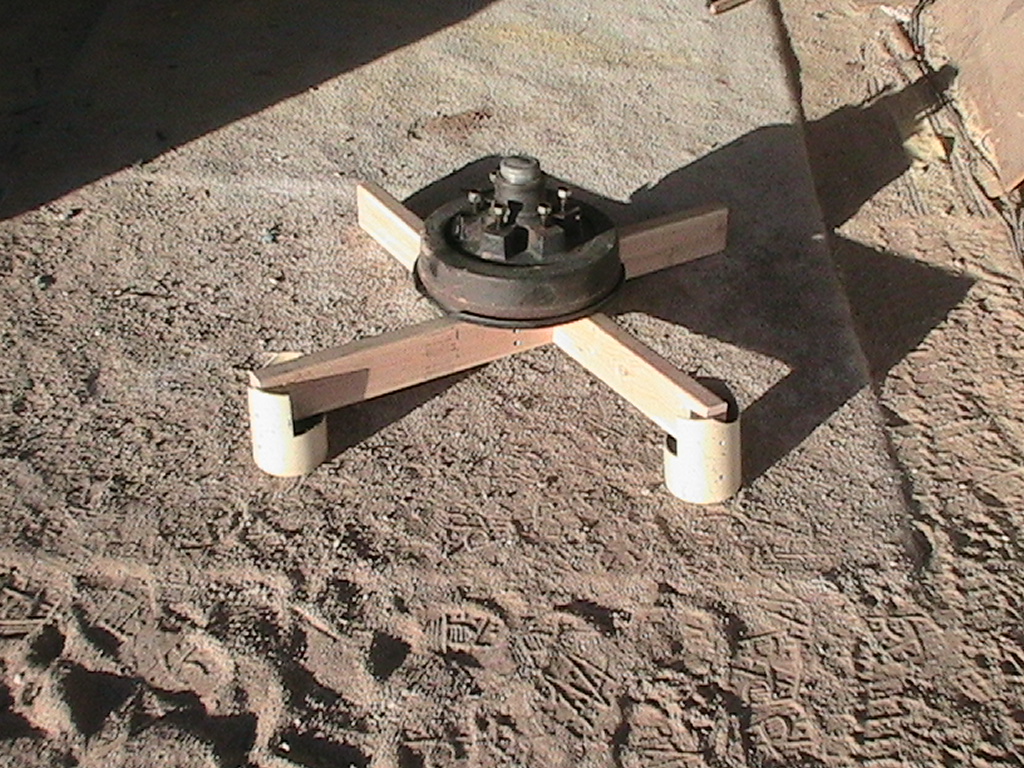 |
Illustrating the PVC "feet" to be used at the corners. |
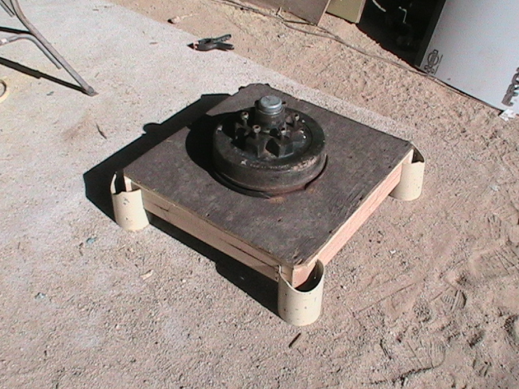 |
The (mostly) completed base unit. PVC feet are not yet attached, nor is the ring for azimuth drive cable. |
 |
Structure from underneath. |
The Table
 |
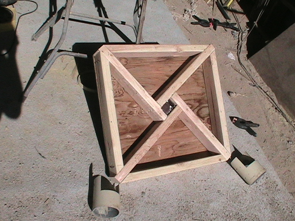
Beginnings of the torsion box to support the chair and OTA. |
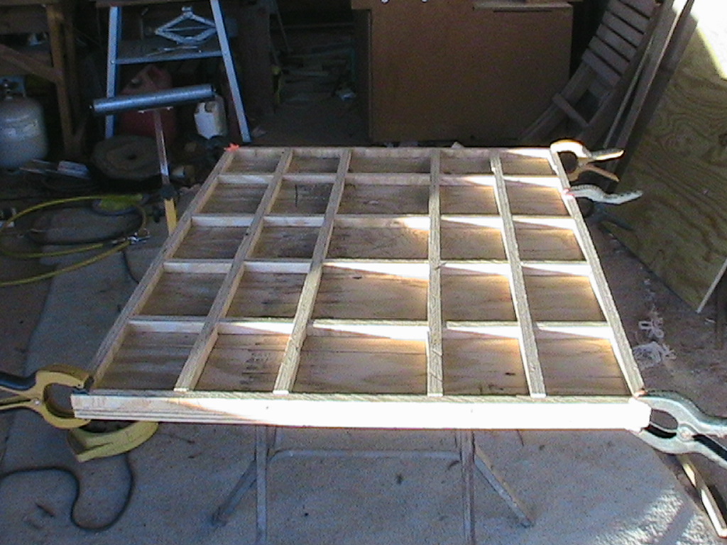 |
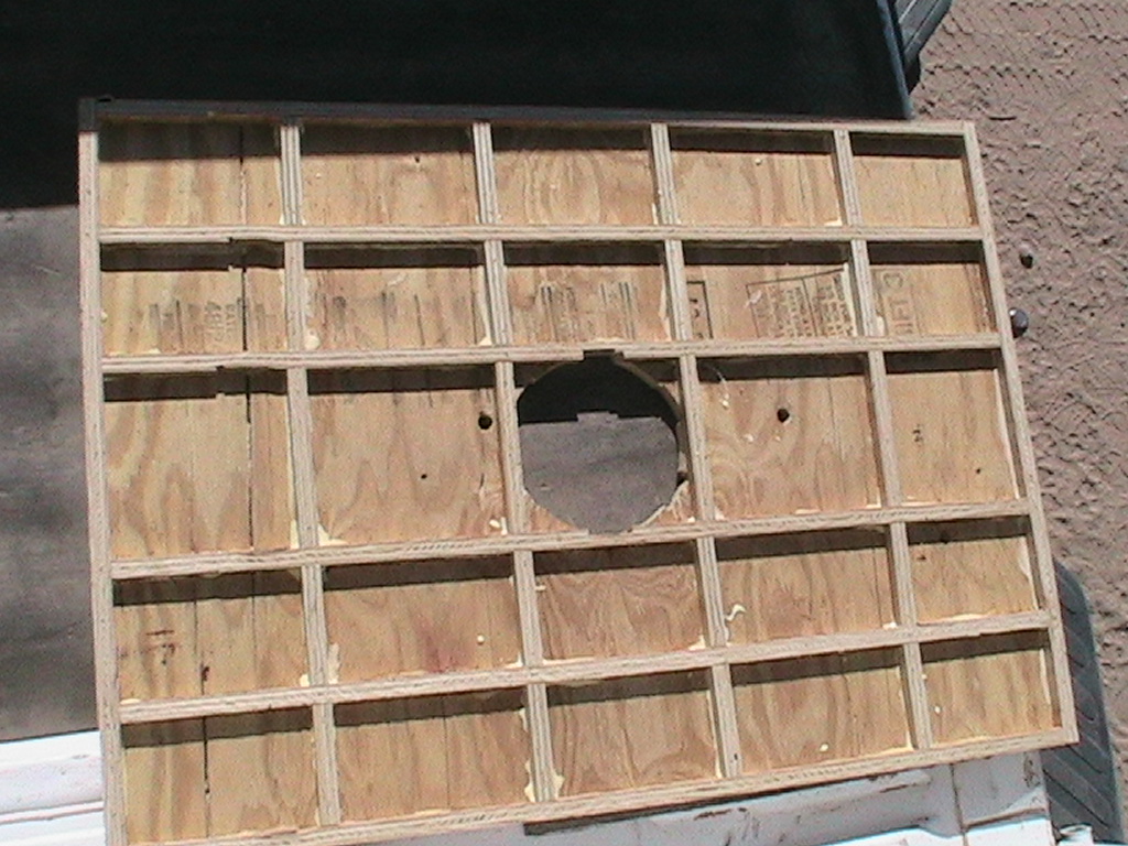
Good image showing the lower sheet of 3/4" plywood and the internal structure that lends the torsion box its strength. The strips are glued to the sheet, and glued to the top sheet, effectively connecting 25 smaller boxes of plywood together, rendering them very very stiff, yet not very thick. |
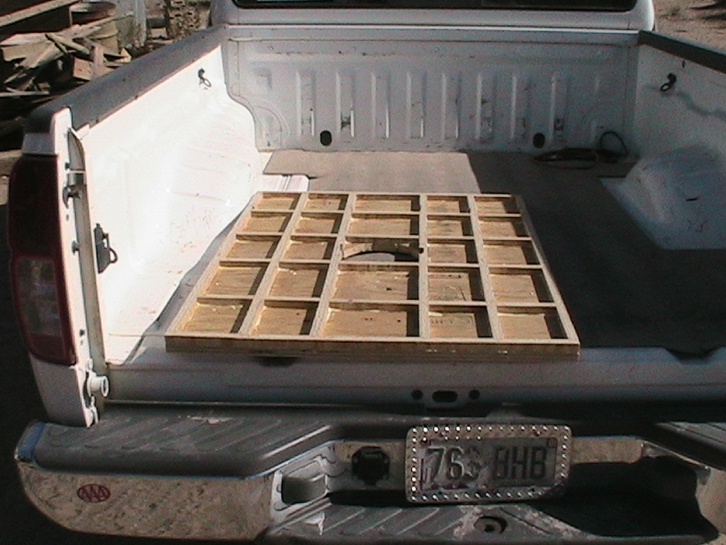 |
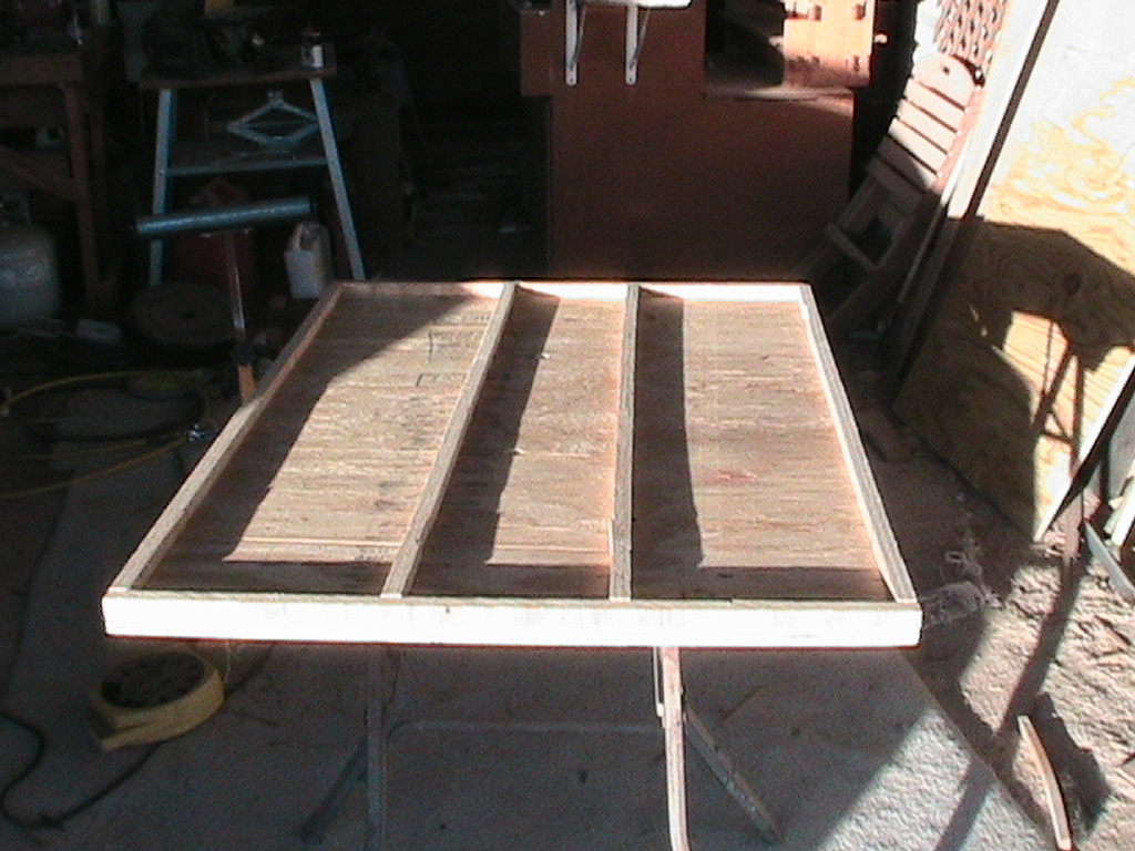
Bottom is glued and drying in the truck bed. |
 |
Each piece was glued and stapled to the bottom sheet to maintain position. |
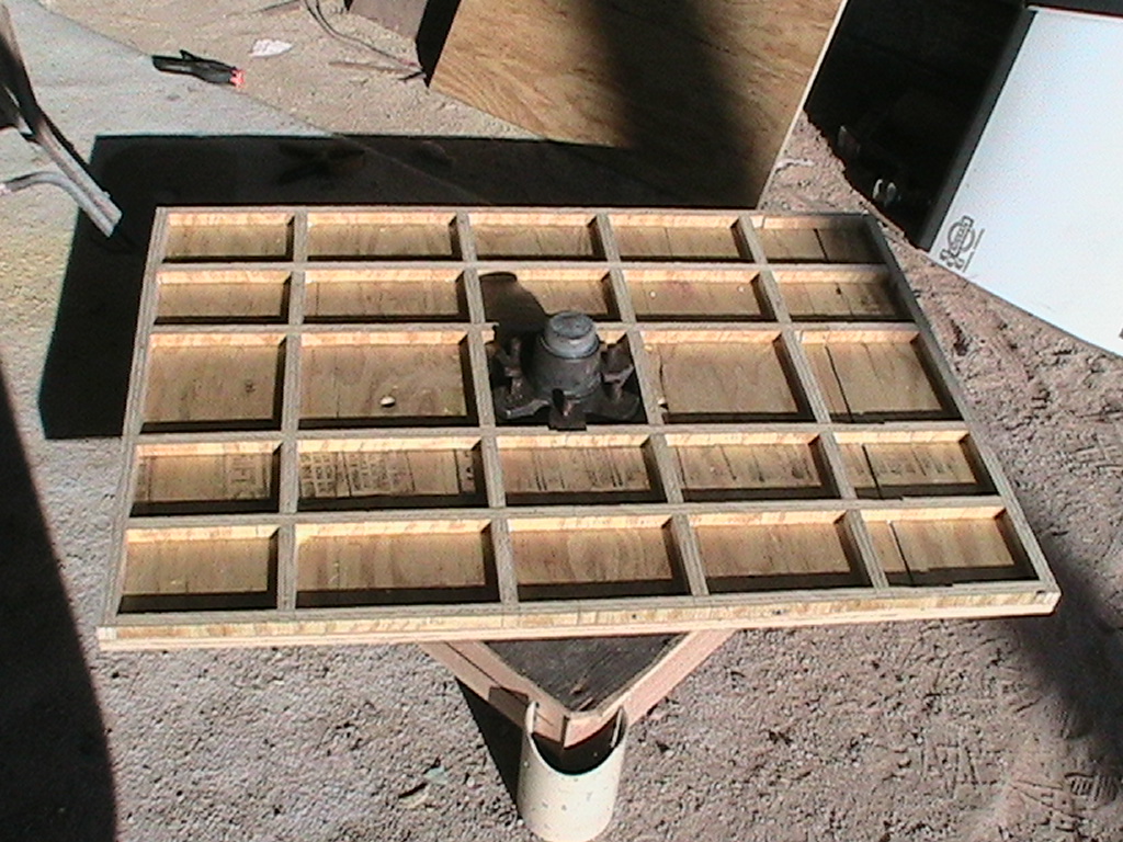 |
Bottom placed on pedestal assembly. |
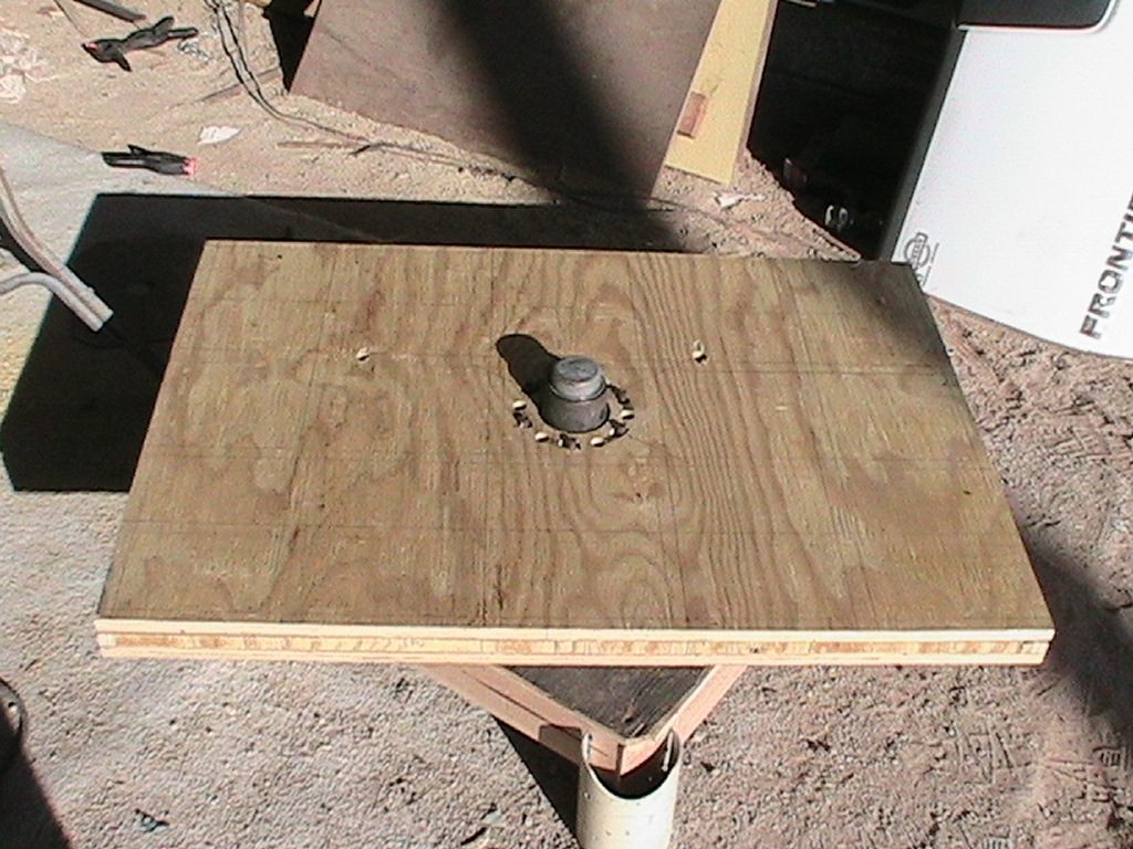 |
Top sheet placed before gluing. |
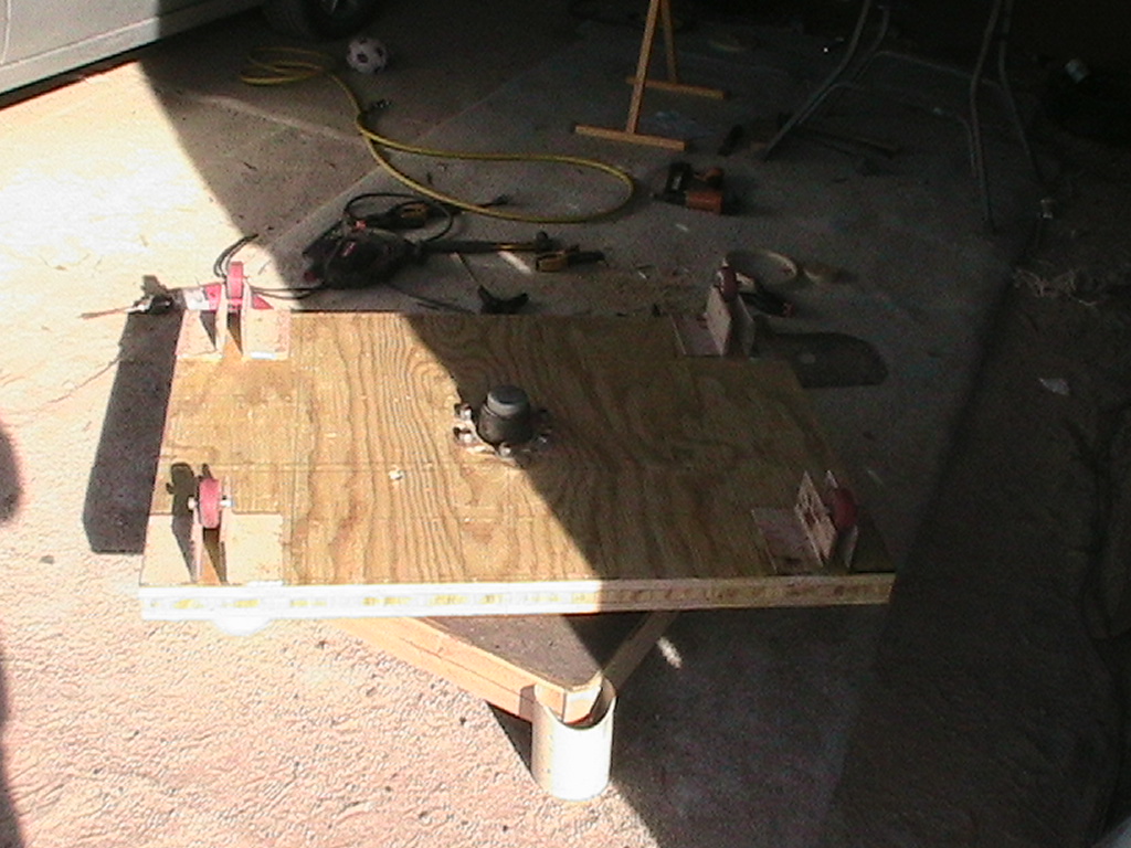 |
Completed torsion box with rollers and steel brackets placed on top. |
 |
Thin! Rosie and I stood on opposite sides after this dried over night. We could detect no flexing or tilting at all. I weigh 213 lbs and she weighs...about half that. :-) |
 |
Close-up of the torsion box shows the staples and guide lines. |
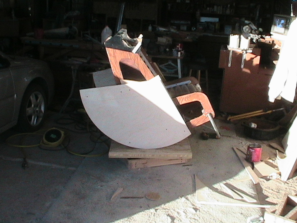
The Main Altitude Bearing
 |
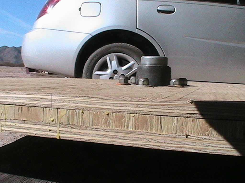
First rough cut of altitude bearing shows scale. Each bearing will be made of a 3/4" layer of plywood glued and screwed to a 1/2" layer, then trimmed to size. This is just the 3/4" slice.
|
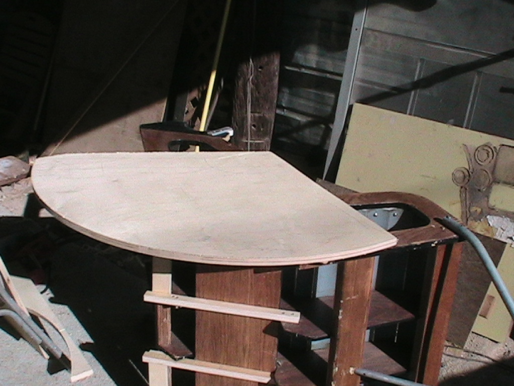
 |
Clamped to the side of the chair, without regard to center of rotation or mass. |
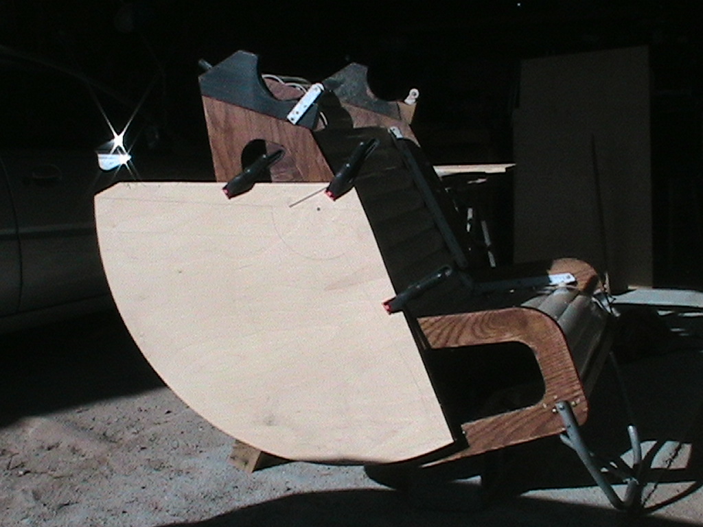
 |
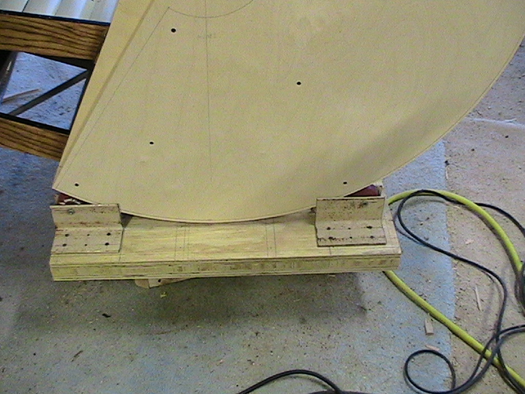
Final cut of the altitude bearings. Both layers are screwed together, and the final outline is visible on the side. Trimming will take place once final placement is made to ease location of center of rotation of the bearing. This shows the "calculated" center of mass, but it may change under further analysis. |
 |
Close-up of the chair sitting on the rollers for the altitude bearing. The steel angle iron is not quite wide enough between because the screws holding the roller wheels need to be slightly longer, so action is not as smooth as I'd like, but it's darn close! |
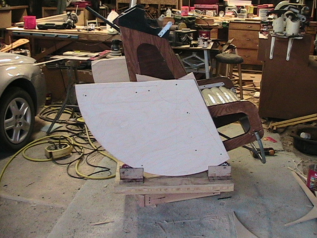 |
Wider shot of the chair on the base. |
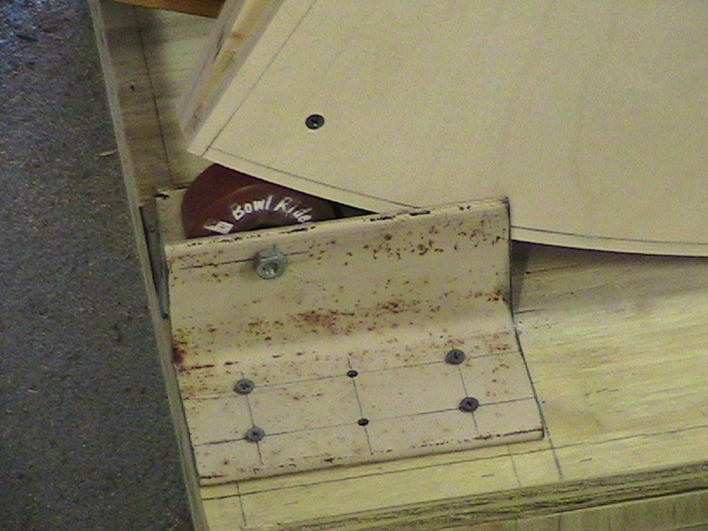 |
Close-up of the foreward portside roller. |
 |
Portside aft roller. |
Fighting problems with a shifting center of gravity, I decided to rebuild the sides of the chair. The problems were
1) People are different.
2) The chair couldn't adapt to different conditions
3) The chair sides didn't have enough material to mount the rail solution.
4) The chair sides also had too many holes in them.
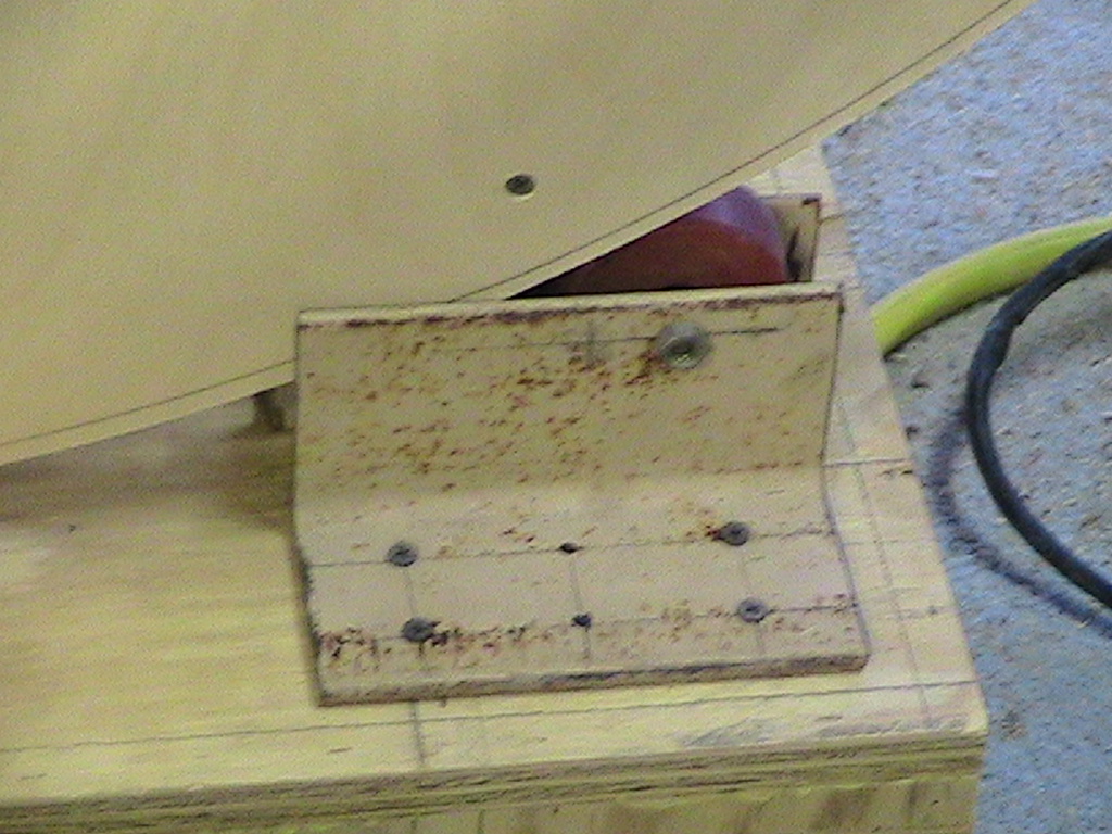
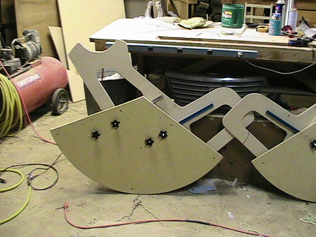
Different people have different distributions of differing amounts of mass. As a more massive person sits in the chair, they shift the center of mass of the whole system. This causes balance and altitude motor loading problems as the load shifts. I came up with a couple solutions. One is to counter the shift by adding weights to the backside of the alt bearings, but this requires I carry many counterweights, and the whole idea was to avoid that. The one I chose was to make the chair and OTA adjustable foreward and backward, to reposition the center of rotation according to the weight of the occupant. I devised a system of T-rails, with bolts through the alt bearings. Two parallel rails will easily accommodate the load, but when I went to mount them on the chair, I found there wasn't enough material there to support them both. I took the chair apart to figure it out and, looking at the individual chair side and seeing all the previous holes, I decided to build new ones with sufficient mounting materials and consistant thickness.
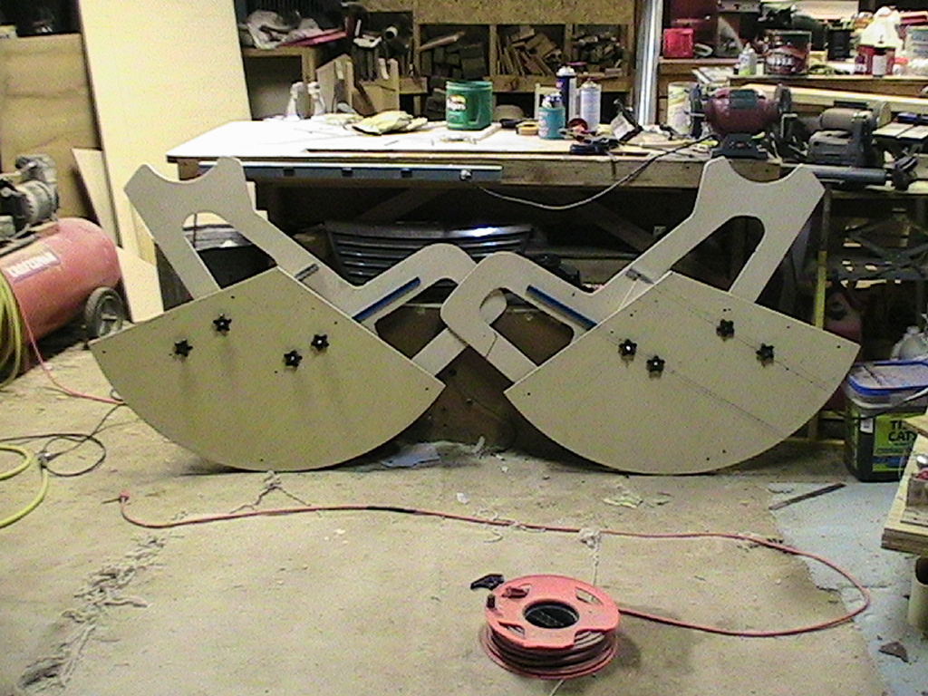 |
The new sides, side by side, ;-) showing the new bearings, the star-bolts that mount to the rails and fasten the bearings to the chair sides. |
 |
A little closer view of one new assembly. |